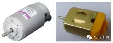
Guide: A DC motor is a rotating electrical machine that converts DC electrical energy into mechanical energy (DC motor) or converts mechanical energy into DC electrical energy (DC generator). It is a motor that converts DC power and mechanical energy to each other.
The working principle of DC motor
A DC motor is a rotating electrical machine that converts DC electrical energy into mechanical energy (DC motor) or converts mechanical energy into DC electrical energy (DC generator). It is a motor that converts DC power and mechanical energy to each other.

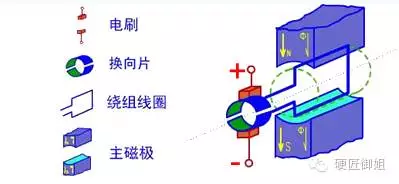
The current DC motors are all of the rotary armature type and are mainly composed of a rotor and a stator. The stator comprises a main magnetic pole, a reversing magnetic pole, a brush device, a base and an end cover; the rotor has an armature core, an armature winding, a commutator, a rotating shaft and a bearing. As the name suggests, the stator is mounted in the stationary part, producing a fixed magnetic field; the rotor, which is the rotating part, produces a magnetic field that changes polarity. This is a physical model diagram for analyzing a DC motor. Among them, the fixed portion has a magnet, which is referred to herein as a main magnetic pole; and the fixed portion has a brush. The rotating portion has a toroidal core and a winding wound around the toroidal core.

A magnetic field is present around the energized conductor, and is subjected to an Ampere force (a force applied to the magnetic field in the magnetic field). Since the direct current is passed, a polarity opposite to that of the main magnetic pole is generated, so that the conductor moves in one direction. When the rotor of the motor is rotated through 180 degrees, the motor brush automatically switches the current direction to keep the rotor rotating. Combined with the magnets that have been played, the same polarity will be repelled, and the opposite polarity will attract, so I understand. This is the basic working principle of DC motors.
Implementation
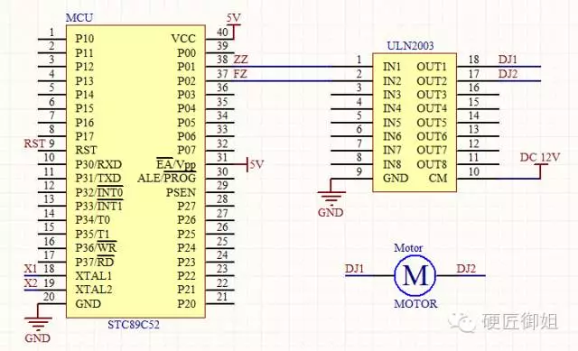
The motor is a current-driven component that requires a large current to pass. The output current of the IO output port of the traditional single-chip microcomputer is generally about 10ma. The current single-chip microcomputer is generally 20-25ma, but the total current of multiple IO ports is limited. Some roots cannot exceed 200ma, and some cannot exceed 400ma. For a DC motor with a rated voltage of 12V and a rated power of 25W, the required operating current is 2A, which is 2000ma. The drive capability of the IO port of the microcontroller is far from enough. Therefore, it is necessary to control the motor by means of a drive device. Here we use ULN2003, which is a high-voltage, high-current, internal driver chip consisting of seven silicon NPN Darlington tubes. Here, you only need to know that the ULN2003 chip can amplify the current output from the IO port of the microcontroller. If the microcontroller wants to drive the motor, it must use the function of a driver like ULN2003.
The DC motor has only two terminals and the wiring is simple. Simply put, one end is connected to the positive pole of the power supply, and the other end is connected to the negative pole, it will rotate; if you want the motor to rotate in the opposite direction, you only need to change the positive and negative poles. The schematic diagram of the connection with the MCU is as follows:


